Achtung! JLog2.5 und HiTec Telemetrie:
Mit JLog2 tritt das nicht in Erscheinung, doch nun, mit JLog2.5, muss vermutet werden, dass HiTec im Empfänger “Angst-Kondensatoren” auf SCL/SDA hat. Zusammen mit zwei kleinen Kondensatoren, die JLog2.5 auch verwendet, führt das zu derart verschliffenen Signalen, dass HiTec-Telemetrie nur noch sporadisch geht.
Wir haben daher seit der letzten Produktionsserie diese Kondensatoren in JLog2.5 weggelassen.
Lauft Ihr in diese Falle, meldet Euch bitte bei mir oder Linus, wir tauschen Euren JLog2.5 um gegen einen ohne die Kondensatoren.
——————————————–
Caution! JLog2.5 and HiTec telemetry:
With JLog2 occurs not in appearance, but now, with JLog2.5, it must be assumed that the HiTec receiver has “anxiety capacitors” on SCL / SDA. Together with two small capacitors also used in JLog2.5 this leads to slurred signals such that HiTec telemetry is only sporadically working.
We have therefore the capacitors omitted in JLog2.5 since the last production series.
If you run into this trap please write to me or Linus, we will exchange your JLog2.5 for one without the capacitors.
.
JLog2 firmwares “Series 4″ have been released now. The firmwares supporting HiTec telemetry correspond to the previous version HSST, T stands for digital temperature sensors (SM#2820) supported at the COM interface of JLog2. The new configurator is JLC5. See Download.
JLog2 forms a HTS-SS HiTec Sensor Station. HiTec’s telemetry bus is I²C, so the two optional pins (K4) of JLog have to be used instead of the COM interface (async serial), whereas COM is used as digital interface to up to 5 temperature sensors (Dallas 1-Wire Bus).
Here is a video of JLog2 with HiTec telemetry in action. – With alarms for mAh, tFET(tPA) and one to five external temperatures, signalled by a 1.0V voltage drop. The voltage limit in JLog (alarm threshold) have to be the same as in the transmitter (voltage alarm). JLog lets the voltage value drop by exactly 1.0V below that threshold to trigger an alarm in the transmitter. Pulsed alarm: 2 seconds on, 5 seconds off. Ubec: Measured by the Rx, alarm threshold by the transmitter. Power calculated by the transmitter.
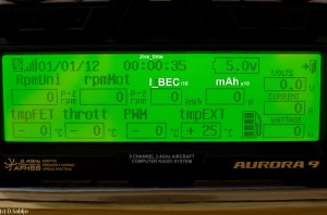
Transmitter’s display
T1: tempFET (0..10n°C) … T2: throttle (0..100%) … T3: PWM (0..100%) … T4: 0(HSS) / extTemp0(HSST) (-40..+215°C) up to 5 temps in log
SPEED: (HSS/HSST) Ibec *10 (11.5A –> 115) … (HSSG2) real speed (km/h)
ALT: mAh /10 (355 –> 3550mAh) … FuelGauge: full..3/4==4, 3/4..1/2==3, 1/2..1/4==2, <1/4==1, empty==0
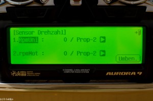
RPM1: rpmUni /10 … RPM2: rpmMotor /10 ……… (Make sure you setup “Prop-2″ for both RPMs.)
Voltage: Ubat, integrated … Current: Imot, integrated …… (Ubec as Rx Voltage from receiver)
Dummy GPS data in display: Latitude, longitude, date (1.1.12). Time is JLog’s relative time, JIVE time (after init) or from JLog’s own time base with JLog-own temperature sensors configured and if no JIVE/CC have been seen.
Constraints:
C50:
- live I: unlimited
- Imax: 60A
- Pmax: @142.5A (U was 49.5V but looks like it is not product dependent (U*I))
C200:
- live I: 200A
- Imax: 200A
- Pmax: unlimited
Values (I, P) in HTS-Navi’s log not delimited.
RPM1, RPM2 in HTS-Navi is *1 whereas it is *10 in transmitter’s display.
In order to have JLog2 recognized by an HiTec Optima receiver on its I²C interface we need to use two 1 to 1.1k pullup resistors on I²C bus lines SCL and SDA against +3.3 volts. 3.3V can be found on JLog’s COM interface (K2-1) or we use a voltage regulator for that. – For all those who do not want to solder, there is JSend, see also here and here. – Here we have JLog2 on HiTec telemetry with a JIVE ESC as virtual multi-sensor and here with a Castle Creations ESC with Castle Link Live, a JCC is used in addition.
JSend is not only providing the pullup resistors against the 3.3V (from COM), than also moving the COM lines to a JR 3-pin interface for connecting of digital temperature sensors SM#2820.
No support of JLog-own digital temperature sensors on COM if the ESC is a Castle Creations. In that case the two digital lines of COM are used for throttle servo pulses, throttle input to JLog2 and output (reversed) to the CC, respectively (bi-directional) as input for the data pulses from the CC ESC (Castle Link Live).
.


