You do not necessarily need to know what the LEDs mean. It can only be helpful if you have a problem.
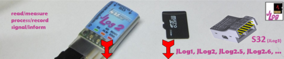
S32 has like JLog four LEDs: red, orange, green, blue.
As with JLog, the software from S32 consists of two parts, which are never executed simultaneously: bootloader, application.
Both software components use the LEDs to signal the user something. So you have to look at the LEDs separately and also describe the transition from bootloader to application.
Bootloader
red: The red LED signals writing to pages of the flash memory of the S32 which only takes place when updating the firmware.
green: S32 is connected via USB.
orange: lights up for every data transfer terminal–S32 via USB.
blue: Data transfer on the data bus if S32 serves as gateway between terminal and a BID.
The two programs, bootloader and application, live in different universes. Since they never run at the same time, they can not communicate with each other at first. They do it by means of a “dead letter box”. The boot loader is the program which communicates with the terminal. The application then only reads the setup from the shared (BL+APP) memory and executes it.
If you plug S32 to USB, it gets operating voltage and starts as usual the bootloader. It looks if there is a USB connect. If so, it goes into its routine for communication with the terminal, if no, it starts the application. It all depends on how quickly the USB host detects an electrical connect and establishes a logical connection to S32. This depends on whether S32 is still in the bootloader at this time, or the application is already running. (If one has for example already an USB SD card reader in one port then the host will connect the S32 on another port of the same hub very quickly. If not, the host reacts slower, - S32 is already in the application).
The application in S32 therefore also recognizes when a USB connect has occurred. It puts a message to the bootloader in the dead mailbox and resets the S32 which then starts into the bootloader. The bootloader does not only look for an actual USB connect, it also sees the message in the mailbox that USB connect is wanted, follows this. – Due to the fact that S32 could already have run the application you can also see different LED show, first the application, then as described above from the bootloader at the USB.
There is another type of message in the dead mailbox, – application to bootloader: That means, “hey, I’m alive”. It could be that a non-executable application was flashed during the update. Then it would be bad if the bootloader would always start the application immediately. If the bootloader does not read an alive message from the application during the powerup of the S32, the boot loader goes to USB on its own, waiting for a connect to allow the terminal to cure it.
The bootloader does not hang waiting on USB forever than only for a few seconds, after which he starts the application what does not leave a life sign. Say, in case of the case you always have a sufficient time window to get an USB connect to the terminal which can cure the application.
This causes a further effect visible on the LEDs: As long as the bootloader waits for an USB connect because of a missing vital sign from the application, the orange LED is flashing.
When you plugged S32 to USB, USB supplied it with voltage, then disconnect and start with RC voltage, the application had not run the last time. This can be seen from the fact that on the first start after an USB connection the orange LED flashes for a while before the application starts, – while the next boot it does not do this anymore, after the bootloader protection routine for the NAND (see below) it starts immediately.
Application
An ARM processor has no EEPROM, instead only a NAND flash, such as a SD card or an USB memory stick (or a SSD). In a NAND cell, one can only change a bit from logical one to zero, not vice versa; one must first delete the cell to make a bit from zero to one. In addition, NAND is organized page-by-page, the page size is device-specific and depends on the position in the addressing range of its NAND. One is also kept doing something against “wear out”, not always writing to the same cells. SD cards, memory sticks, SSDs and eMMCs have a controller, so you can see the NAND (there is also NOR) cells simply as an array of bytes. In a processor you have to do this however “barefoot”, by software. This is what S32 if doing for the storage area where the setup goes to.
There are, however, also quite specific cells in the memory that S32 must write to as early as to the above-mentioned virtual EEPROM after powerup.
How to successfully write a NAND without destroying its contents unintentionally (always a whole page!) depends, above all, on the voltage that is assumed to be provided to the NAND at the moment of writing. You have to set up the NAND accessing mechanisms accordingly before writing.
Now the circle closes: In RC one can expect everything, above all insanity on the operating voltage for S32 and thus for its NAND in the processor. …Voltage comes from the BEC of an ESC, anti-sparc does not exist or does not work, user frightened, – and already we have the most beautiful operating voltage “wiggle”.
Therefore, in the bootloader a fairly complex process takes place after POR (Power On Reset) in order to protect the NAND but in time to perform the necessary writing in it (see “dead mailbox”). It becomes complex if S32 connects to the USB host at the same time, which wants to be served just-in-time, otherwise it will give up. During this time you see the four LEDs red to blue in ascending sequence go, then descending again. This is still the bootloader, the LED cinema of the application follows only after:
Setup-independent, the application does only one with the LEDs: It lights them up all at the same time, red|orange|green |blue for half a second, then off again. This means: Hello, here the application, I just started.
What follows now depends on the setup – mainly the selected ESC (only in one case on the telemetry: Futaba), the LogStop and the occurrence of an alarm condition, as well as on activity on the data bus. To Futaba, concerns red and blue, you can read in the above link. Otherwise:
red: Should never go on, means fatal error on the part of the file system on the SD card.
orange: Flashes for each write operation to the SD. Continuous lighting means that one of the configured alarm thresholds triggered an alarm.
green: signals data traffic with the ESC
blue: signals traffic with a device on the data bus
..
Because of these love letters between application and bootloader it is not necessary that S32 was powerless before you plug in USB. S32 always recognizes USB and always starts talking to the terminal.